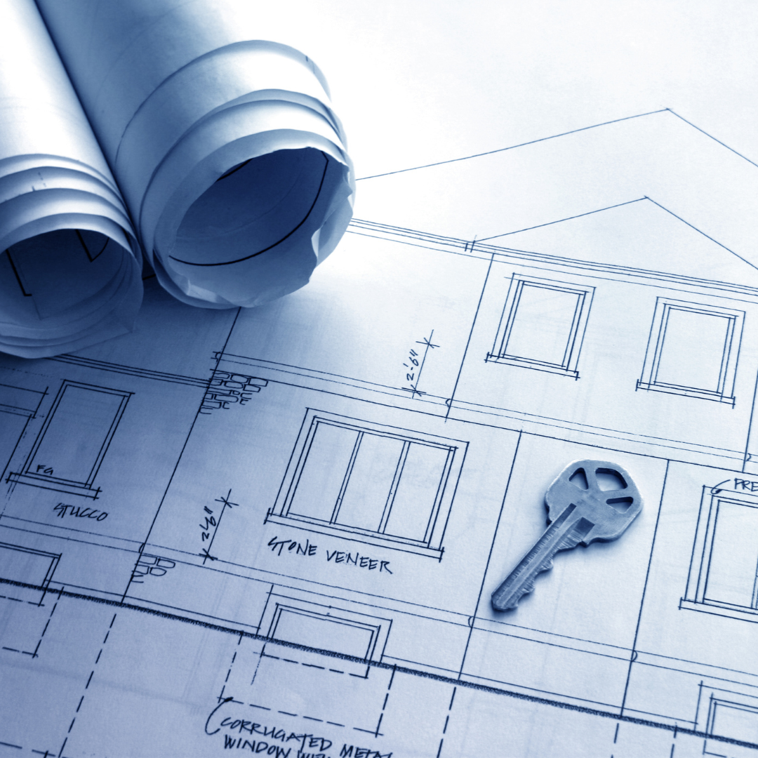
ARCHITECTURAL DRAWINGS
Architectural drawings are visual representations of a building or structure that communicate design ideas, dimensions, and construction details. They are typically created by architects, engineers, or drafters to convey the intent and specifications of a project to clients, contractors, and other stakeholders involved in the construction process.

Architectural drawings can take various forms, but some common types include:
Site Plans: Site plans show the entire property where the building is situated, including the building footprint, parking areas, landscaping, utilities, and other site features. They help understand how the building should be placed on the site.
Foundation Plans: A foundation plan shows the layout and details of a building's foundation. It includes information about footings, foundation walls, columns, slabs, and other structural elements.
The plan helps ensure that the building's weight is properly supported and transferred to the ground. It is an important reference for contractors and construction teams to accurately implement the design and maintain the building's structural integrity.
Floor Plans: These drawings provide a top-down view of a building, showing the layout and arrangement of rooms, walls, doors, and windows. Floor plans are essential for understanding spatial relationships and flow within a structure.
Roof Plans: A roof plan provides a detailed view of the layout and design of a building's roof. It shows the shape, dimensions, and slopes of the roof, as well as the positioning of various elements such as ridges, valleys, hips, and dormers.
The roof plan also indicates the materials to be used, such as roofing tiles or shingles, and may include additional details such as drainage systems, vents, and skylights.
This drawing is essential for accurately constructing the roof and ensuring proper waterproofing, structural integrity, and overall aesthetic appearance of the building.
Sections: Sections are drawings that cut through a building vertically or horizontally, revealing the internal details and relationships between different floors, spaces, and structural elements. They help understand the building's internal structure, such as wall thickness, ceiling heights, and the arrangement of elements within.
Elevations: Elevations depict the exterior views of a building from different sides, showing the height, proportions, and architectural features of the facades. They convey the visual appearance and style of the structure.
Schematic electrical layout: Is a drawing that shows the schematic arrangement and placement of electrical components in a building. It includes outlets, switches, light fixtures, and wiring routes. This plan guides electricians during installation and ensures the electrical system is designed properly.
Schematic clean and foul water layout: This is a drawing that shows the arrangement of clean water supply and foul water drainage systems in a building. It indicates the location of fixtures, pipes, and drains for water supply and wastewater disposal.
This plan guides plumbers and contractors ensuring proper water distribution and drainage.
Door and window schedule: This document provides detailed information about the doors and windows used in a building. It includes specifications like location, dimensions, materials, and special features for each door and window.
This schedule serves as a reference for contractors and installers to ensure accurate and consistent installation throughout the building.
Floor finishes and furniture layout: Floor finishes refer to the materials used to cover the floor surfaces, such as carpet, tiles, hardwood, vinyl, or concrete. They are chosen based on factors like aesthetics, functionality, durability, and maintenance.
Furniture layout involves arranging furniture within a space to create an efficient and visually pleasing arrangement. Factors considered include the room's size, shape, function, and occupants' needs. Both floor finishes and furniture layout contribute to the functionality and aesthetics of a space.
Construction Details: Detail drawings zoom in on specific elements of a building, such as windows, doors, staircases, or structural connections. They provide enlarged and highly specific information on how these components are constructed and installed.
Renders: These are visual representations of the building's exterior or interior, often created with computer software. They provide a realistic or stylized depiction of how the finished project will look.
Architectural drawings are typically created using computer-aided design (CAD) software, which allows for precise measurements, scale representations, and efficient editing and collaboration.
STRUCTURAL DRAWINGS
Structural drawings are a set of drawings that depict the structural elements and systems of a building. They provide detailed information about the building's load-bearing components, such as beams, columns, walls, slabs, and foundations.
The purpose of structural drawings is to communicate the design and construction requirements to engineers, contractors, and construction teams involved in the project.
These drawings are typically created by structural engineers and work in conjunction with architectural drawings to ensure that the building is structurally sound and meets safety standards.

Some common types of structural drawings include:
Structural Plans: These drawings show the layout and dimensions of structural elements, including columns, beams, and walls. They illustrate the structural framework of the building and how the loads are distributed.
Foundation Plans: Foundation plans depict the layout and details of the building's foundation, including footings, foundation walls, and slabs. They ensure that the building is properly supported and anchored to the ground.
Structural Details: These drawings provide enlarged and specific information about connections, joints, and reinforcement within the structural elements. They ensure proper construction techniques and structural integrity.
Structural Sections: Sections cut through the building vertically or horizontally to reveal the internal details of the structure. These drawings show the arrangement of structural components and their relationship to other building elements.
Structural Notes and Schedules: These documents accompany the drawings and provide additional information such as material specifications, load capacities, and construction details.
Calculations: Calculations in structural drawings are mathematical calculations performed by structural engineers to determine the dimensions, sizes, capacities, and other technical aspects of structural elements within a building.
These calculations help determine the appropriate sizes of beams, columns, slabs, and foundations based on anticipated loads. They also determine the required amount and configuration of reinforcement bars in reinforced concrete structures.
The calculations ensure that the structure is safe, structurally sound, and compliant with building codes and regulations.
Bar bending schedule (BBS): is a document or chart that provides detailed information about the reinforcement steel bars used in a reinforced concrete structure.
It includes details such as the size, shape, length, and arrangement of the bars, as well as instructions for their fabrication and placement during construction.
The BBS ensures that the reinforcement bars are correctly installed according to the structural design and engineering specifications, promoting the structural integrity and strength of the concrete structure.
MECHANICAL DRAWINGS
Mechanical drawings also known as MEP (Mechanical, Electrical, and Plumbing) drawings, are a set of technical drawings that depict the mechanical systems and components within a building.
These drawings provide detailed information about heating, ventilation, air conditioning (HVAC), plumbing, fire protection, and other mechanical systems. Mechanical drawings are typically created by mechanical engineers or MEP consultants.

Some common types of mechanical drawings in architecture include:
HVAC Drawings: These drawings illustrate the layout and specifications of the heating, ventilation, and air conditioning systems within a building. They depict the location of HVAC equipment, such as air handling units, ductwork routes, diffusers, and thermostats.
Plumbing Drawings: Plumbing drawings detail the water supply, drainage, and waste disposal systems within a building. They indicate the location of plumbing fixtures, such as sinks, toilets, showers, and pipes, along with details on pipe sizes, slopes, and connections.
Fire Protection Drawings: These drawings show the layout and design of fire protection systems, including fire sprinklers, fire alarms, and fire suppression systems. They specify the location of fire safety equipment, such as smoke detectors, sprinkler heads, and fire extinguishers.
Electrical Drawings: Although technically categorized under electrical drawings, electrical plans are often included within the MEP set of drawings. These drawings depict the location of electrical outlets, switches, lighting fixtures, and power distribution panels within the building.
Mechanical drawings play a crucial role in ensuring the proper installation and coordination of mechanical systems within a building. They provide contractors with detailed information on equipment placement, routing of ducts and pipes, and system connections.
These drawings contribute to the overall functionality, energy efficiency, and safety of the building by facilitating the accurate implementation of mechanical systems.
BIILS OF QUANTITIES (BOQ)
BOQs are detailed documents prepared by quantity surveyors or estimators that provide a comprehensive list of materials, labor, equipment, and other resources required for the construction or building project.
BOQs are typically organized by trade or work package and provide a breakdown of quantities and costs associated with each element of the project. The purpose of bills of quantities is to facilitate accurate cost estimation, procurement, and tendering processes.
They serve as a basis for preparing construction contracts, obtaining quotations from suppliers and subcontractors, and assessing the overall project cost.

A typical bill of quantities includes the following information:
Itemized List: The bill of quantities lists all the items or work packages required for the project, such as foundations, walls, flooring, electrical installations, plumbing, and finishing elements.
Quantities: Each item in the bill of quantities is quantified, specifying the exact quantities required for materials, labor, or other resources. These quantities can be expressed in units of measurement such as square meters, cubic meters, linear meters, or individual quantities.
Specifications: The bill of quantities may include specifications or references to technical documents that define the quality, standards, and requirements for each item or work package.
Pricing: The bill of quantities may provide unit rates or prices for each item or quantity, allowing for cost calculations. These rates may be based on market rates, historical data, or specific project pricing agreements.
Summary Totals: The bill of quantities includes summary totals that provide an overview of the overall costs for each work package and the total project cost.
Bills of quantities are utilized by contractors, suppliers, and project stakeholders for several purposes. They enable accurate cost estimation, help in the preparation of tenders and contract negotiations, assist in material procurement and resource planning, and provide a basis for monitoring and controlling project costs during construction.
By providing a detailed breakdown of project requirements and associated costs, bills of quantities contribute to effective project management and ensure transparency and accountability in the construction process.


1 comment
Abednego Dakpo
I want a way of doing building quantities of a design drawings
Leave a comment
This site is protected by hCaptcha and the hCaptcha Privacy Policy and Terms of Service apply.